Ram Air Intake
ZX-25R has become a phenomenon even before its release .Now we have the following information on essential patents that Kawasaki has filed.
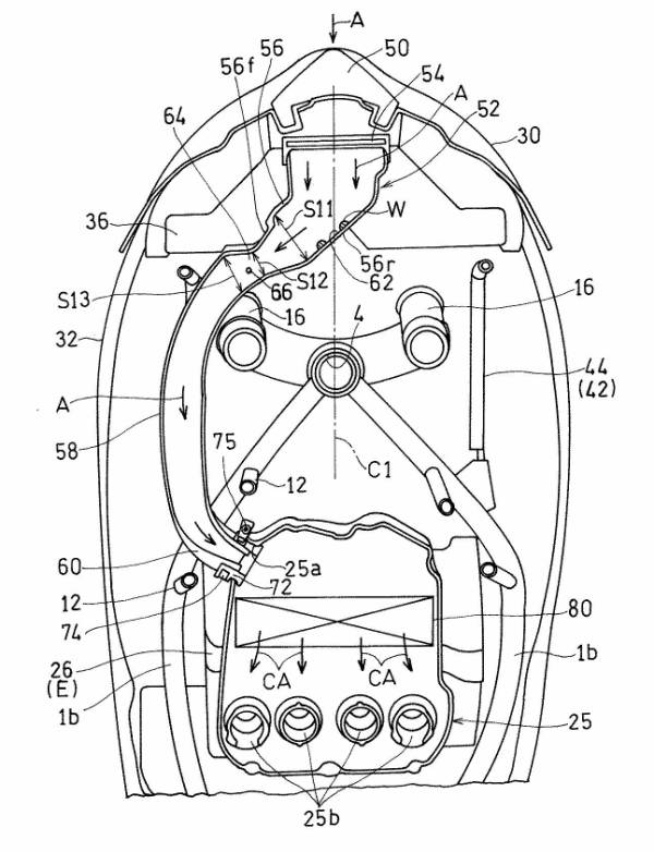
Kawasaki filed the Ram Air intake patent in June 2018.
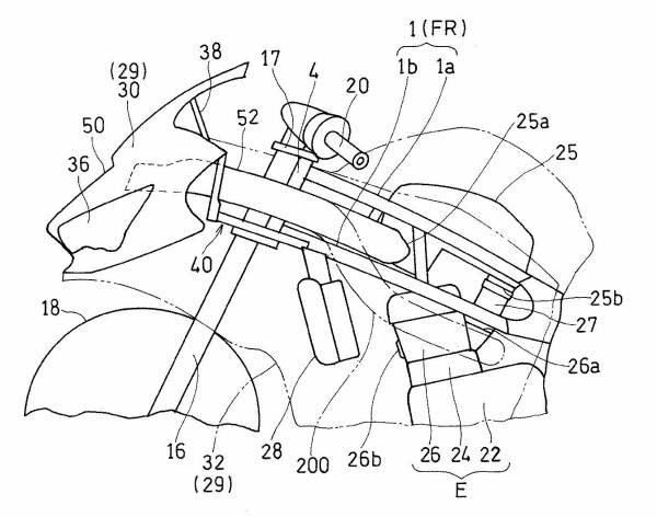
- 25: Air cleaner
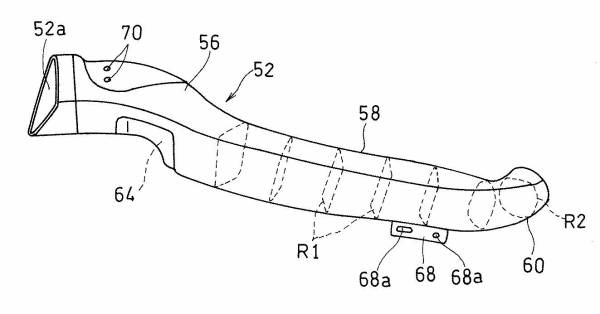
- 52: Intake duct
- 52a: Inlet duct entrance
- 56: Duct front
- 58: Middle part of the duct
- 60: Rear of duct
- 62: Adhering part
“Provide a straddle-type vehicle that can efficiently introduce air into the air cleaner.”
The straddle-type vehicle of the present invention disposed above the engine between left, as well as right frames, extends backward from the head pipe .
A front cowl covers the front of the head pipe, and the pair of left and right main-frames.
An air cleaner, a front fork rotatably supported by the head pipe. And an intake duct that takes in a running wind from a front end inlet and supplies the air to the air cleaner.
The intake duct including the head pipe and the front fork .A duct front portion disposed in front of the duct, a duct intermediate portion extending rearward.
The Patent
That is from the duct front portion in the vehicle width direction of the front fork and the main-frame . And a curve inward in the vehicle width direction from the duct intermediate portion.
A duct rear portion connected to the air cleaner . And an inlet of the intake duct is arranged in a vehicle width direction of the vehicle.
The duct front part is located on a line and faces the air intake opening opened to the front of the front cowl. And the duct front part is curved to one way in the bike wide direction from front end entrance to the rear .
And the inner wall surface of the duct front part. A part of which forms an adhering portion where air introduced from the inlet collides to adhere moisture. “
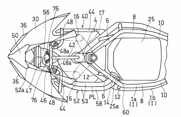 Above diagram shows the top view. By the wasy there was no duct present. It is from different genre but the presence of Z H2 and SC array is felt.
Air Cleaner Patent
This patent too was filed in June 2018 by Kawasaki.”Provide a straddle-type vehicle with stable air tank capacity and stable fuel tank support.”
The straddle-type vehicle includes a pair of left and right main frames 1 extending rearward from the head pipe 4 .
An air cleaner 25 disposed above the cylinder head 26 of the engine E between the left and right main frames 1. And an air cleaner 25.
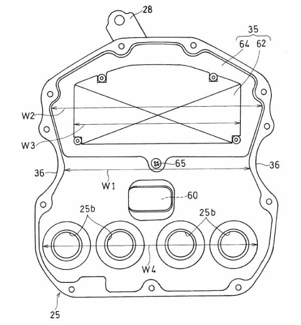
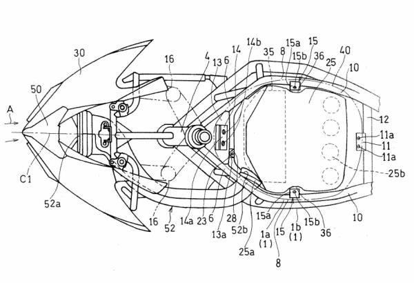 A fuel tank 40 is provided on the upper side and recesses 36 recessed inward in the vehicle width direction are formed on both sidewalls. In the vehicle width direction of the cleaner case 34 of the air cleaner 25.
The fuel tank 40 is supported. The tank support portion 15 is provided so as to protrude inward in the vehicle width direction. That is from the left and right main frames 1, and is disposed in the recess 36. “
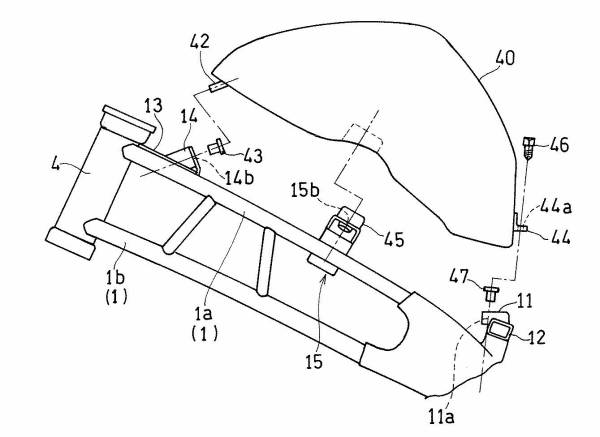
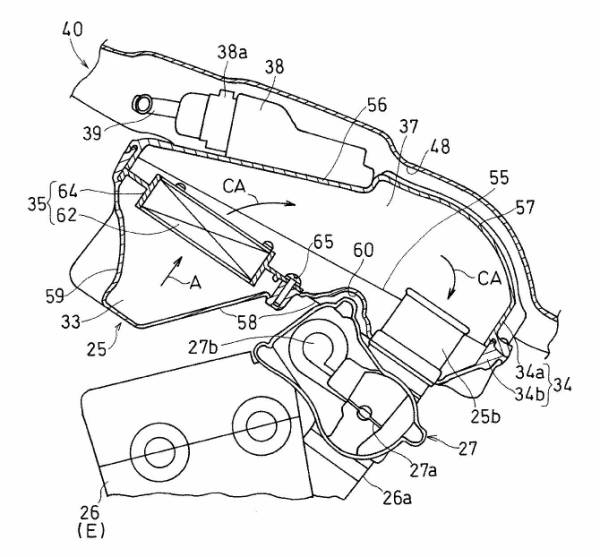
According to this configuration, the fuel tank is stably supported since the portion having the largest width dimension is supported by the tank.
Support portion in the middle portion in the front-rear direction of the fuel tank. By simply installing the air cleaner, the overall width of the cleaner case in the vehicle width direction will not change .
So the capacity of the air cleaner can be secured. “
- 40: Fuel tank
- 38: Electronic control unit (probably ECU)
- 27: Throttle body
- 25: Air cleaner
- 35: Cleaner element
Top view of Air Cleaner
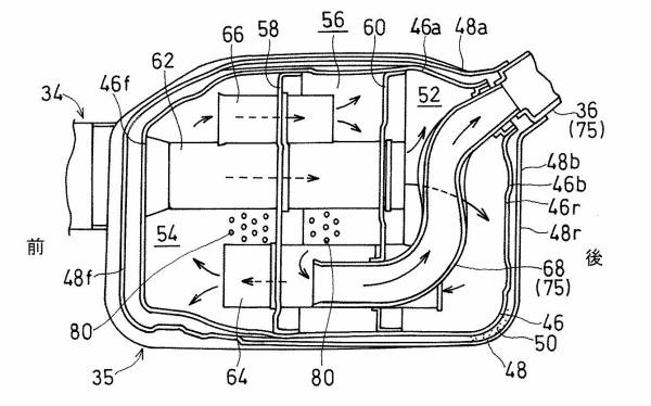
Muffler Patent
“It is an object to provide an exhaust device for a saddle-ride type vehicle in which heat and sound are hardly transmitted from the inner case to the outer case.”
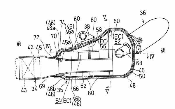
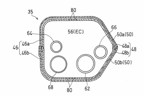
The muffler 35 includes an inner case 46 in which an expansion chamber EC is formed, an outer case 48 that covers the inner case 46.
And a sound absorbing material 50 that is interposed between the inner case 46 and the outer case 48. The inner case 46 is formed by joining a pair of inner case halves 46a and 46b .
And the outer case 48 is formed by joining a pair of outer case halves 48a and 48b.
A through hole 80 is formed to communicate the expansion chamber EC and the sound absorbing material 50. An inner case 46 and an outer case 48 are joined to an inflow pipe 45 that introduces exhaust gas into the expansion chamber EC.
The inner case 46 and the outer case 48 are joined to the outflow pipe 75 for leading the exhaust.
This is a patent filed in June 2018.
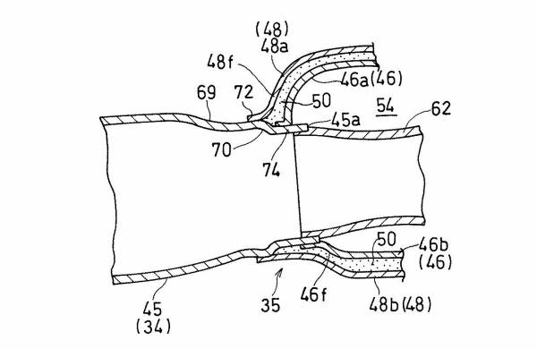 According to this configuration, since the inner case and the outer case are not in contact with each other, the heat of the exhaust and the vibration sound of the exhaust are not transmitted from the inner case to the outer case.
This effectively prevents the heat damage caused by the exhaust device. And the deterioration of the outer case is suppressed.
- 46: Inner case
- 48: Outer case
- 50: Sound absorbing material
Source : Google Patents
See Also
Honda CBR600RR may hit market soon
2020 Kawasaki Z1000R
Honda “CB4X” Concept
Brough and Astons Motorcycle


